Specifications
800G QSFP-DD Transceivers for High-Performance Networks
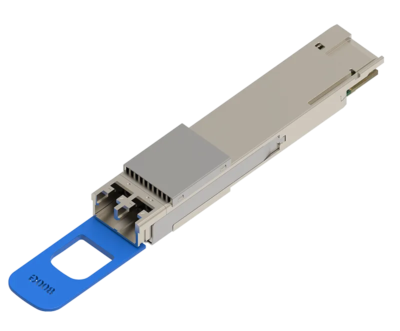
Reliable, high-density 800G optical connectivity designed for modern data centers, cloud networks, AI and machine-learning fabrics, high-performance computing environments, campus networks, inter-building connections, and switch-to-switch interconnects. The E.C.I. NETWORKS EN-QDD800-2LR4-2CS combines two 400GBASE-LR4 optical interfaces within a single hot-pluggable QSFP-DD transceiver.
Key Features
- Hot-pluggable QSFP-DD 76-pin form factor
- 800 Gigabit Ethernet aggregate data rate
- Supports 1×800G and 2×400G operating configurations
- Two 400GBASE-LR4 optical interfaces
- Eight electrical lanes operating at 106.25 Gb/s per lane
- Eight optical lanes arranged as two four-lane CWDM groups
- 53.125 GBd PAM4 signaling per lane
- Four CWDM wavelengths per 400G LR4 interface
- EML transmitters with thermoelectric cooling
- PIN photodiode receivers
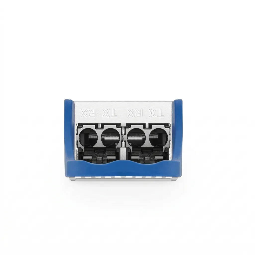
- Dual duplex CS optical connectors
- Up to 10 km transmission over single-mode fiber
- 400GAUI-4 electrical interface
- IEEE 802.3cu-2021 compliant
- QSFP-DD Hardware Revision 6.3 compliant
- CMIS Revision 5.2 compliant
- Integrated digital diagnostic monitoring
- Two-wire serial management interface
- Low-EMI design and ESD protection
- Single 3.3 V power supply
- Maximum power consumption of 16 W
- Power Class 8
- Commercial operating temperature: 0°C to +70°C
- Storage temperature: −40°C to +85°C
- RoHS 6 compliant
800G QSFP-DD 2×400G LR4 Optical Transceiver with Dual CS Connectors
The EN-QDD800-2LR4-2CS is a high-performance 800GbE QSFP-DD optical transceiver designed for single-mode fiber links up to 10 km. The module incorporates two 400GBASE-LR4 optical engines within one hot-pluggable 76-pin QSFP-DD package.
The transmitter section includes two four-channel EML laser arrays, two four-channel drivers, and a shared digital signal processor. The receiver section includes two four-channel PIN photodiode arrays, two four-channel transimpedance amplifiers, and the shared DSP.
Eight 106.25 Gb/s PAM4 electrical input lanes are converted into eight optical signals organized as two groups of four CWDM wavelengths. Each four-wavelength group is multiplexed into one 400G LR4 transmit path. On the receiver side, each incoming 400G LR4 signal is demultiplexed into four optical lanes and converted back into four PAM4 electrical output lanes.
| Parameter | Specification | Parameter | Specification |
|---|---|---|---|
| Part Number | EN-QDD800-2LR4-2CS | Product Type | 800G QSFP-DD 2×400GBASE-LR4 optical transceiver |
| Form Factor | Hot-pluggable QSFP-DD | Host Connector | 76-position QSFP-DD host interface |
| Aggregate Data Rate | 800Gb/s | Supported Configurations | 1×800G and 2×400G |
| Per-Lane Data Rate | 106.25 Gb/s PAM4 | Signaling Rate | 53.125 GBd per lane |
| Electrical Lane Configuration | Eight PAM4 host lanes | Optical Lane Configuration | Eight optical lanes arranged as two four-lane CWDM groups |
| Modulation | PAM4 | Electrical Interface | 400GAUI-4-based interface |
| Optical Interfaces | Two 400GBASE-LR4 interfaces | Application | 2×400GBASE-LR4 |
| Standards Compliance | IEEE 802.3cu-2021, QSFP-DD Hardware Rev. 6.3, CMIS Rev. 5.2 and RoHS 6 | Management Standard | CMIS Revision 5.2 |
| Nominal Wavelengths | 1271, 1291, 1311 and 1331 nm per 400G interface | Number of Wavelengths | Four wavelengths per 400G engine; eight optical lanes total |
| Wavelength Ranges | 1264.5–1277.5 nm, 1284.5–1297.5 nm, 1304.5–1317.5 nm and 1324.5–1337.5 nm | Optical Architecture | Two four-wavelength CWDM optical engines |
| Transmitter Type | EML transmitters with TEC | Detector Type | PIN photodiode receivers |
| Optical Connector | Dual CS connectors | Connector Configuration | Two duplex optical interfaces |
| Fiber Type | Single-mode fiber | Maximum Reach | Up to 10 km over SMF |
| Typical Cabling | Two duplex CS single-mode connections | Link Configuration | Two 400G LR4 optical links |
| Average Transmit Power | −2.7 to +5.1 dBm per optical lane | Total Average Launch Power | Maximum 11.1 dBm |
| Minimum Transmitter OMAouter | +0.3 dBm for TDECQ below 1.4 dB; otherwise TDECQ − 1.1 dBm | Maximum Transmitter OMAouter | +4.4 dBm per lane |
| Maximum TDECQ | 3.4 dB per lane | Extinction Ratio | Minimum 3.5 dB |
| Transmitter Lane-Power Difference | Maximum 4.0 dB between any two lanes | Side-Mode Suppression Ratio | Minimum 30 dB |
| Optical Return-Loss Tolerance | 15.6 dB | Transmitter Reflectance | Maximum −26 dB |
| Relative Intensity Noise | Maximum −136 dB/Hz | Maximum Transition Time | 15 ps in long mode; 10 ps in short mode |
| Average Receive Power | −9.0 to +5.1 dBm per lane | Maximum Receive OMAouter | +4.4 dBm per lane |
| Receiver Sensitivity | Maximum of −6.8 dBm or SECQ − 8.2 dBm, OMAouter per lane | Stressed Receiver Sensitivity | −4.8 dBm OMAouter per lane |
| Receiver Overload | Minimum +5.1 dBm average power per lane | Optical Damage Threshold | +6.1 dBm |
| Receiver Lane-Power Difference | Maximum 4.3 dB OMA between any two lanes | Receiver Reflectance | Maximum −26 dB |
| LOS Assert Threshold | −20 dBm | LOS Deassert Threshold | −10.8 dBm |
| Approximate Average-Power Budget | Approximately 6.3 dB per lane | Approximate Low-TDECQ OMA Budget | Approximately 7.1 dB per lane |
| FEC | Not explicitly specified in the datasheet; verify host-platform requirements | Breakout Capability | Supports 2×400G operation according to the module EEPROM |
| Management Interface | Two-wire serial interface | Digital Diagnostics | Integrated DDM/DOM functionality |
| Temperature-Monitor Accuracy | ±3°C | Transmit-Power Monitor Accuracy | ±3 dB |
| Receive-Power Monitor Accuracy | ±3 dB | Supply-Voltage Monitor Accuracy | ±3% |
| Bias-Current Monitor Accuracy | ±10% | Module Initialization Time | Maximum 2000 ms |
| Power Supply | 3.3 V nominal | Supply Range | 3.135 to 3.465 V |
| Maximum Power Consumption | 16 W | Module Power Class | Power Class 8 |
| Typical Supply Current | 5104 mA | Maximum Instantaneous Peak Current | 6400 mA for less than 50 μs |
| Operating Temperature | 0°C to +70°C | Storage Temperature | −40°C to +85°C |
| Relative Humidity | 5% to 85%, non-condensing | ESD Rating | 1000 V |
| Environmental Compliance | RoHS 6 | Primary Applications | Data centers, AI fabrics, HPC networks, campus links, aggregation, and switch or router interconnects |
Connectivity examples

800G to 800G Direct Connectivity
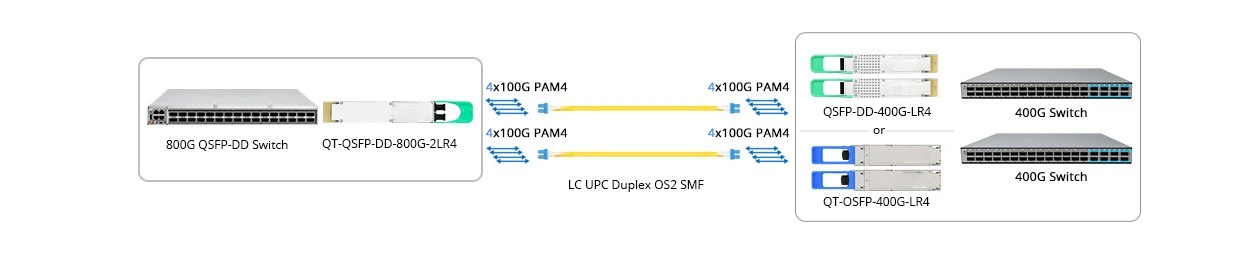
800G to 2x 400GE Breakout Connectivity
Selection Guide
Which 100G Transceiver Should I Choose? Selecting the right 100G transceiver depends on distance, fiber type, and infrastructure. Use the guide below to quickly identify the best option for your deployment.
| Selection Criteria | Option | Recommended Transceiver | Fiber / Connector | Typical Use Case |
|---|---|---|---|---|
| Host Form Factor | QSFP-DD800 | QDD800-DR8-M16, QSFP-DD800 SR8, 2 × FR4 or 2 × LR4 | 76-position QSFP-DD host interface | High-density switches, routers, cloud platforms and AI fabrics |
| Host Form Factor | OSFP | OSFP DR8, SR8, 2 × FR4, 2 × LR4 or coherent optics | OSFP host interface; not interchangeable with QSFP-DD800 | Platforms designed specifically for OSFP modules |
| Distance | Up to 50 m | 800GBASE-VR8 or short-reach SR8 | OM4/OM5 multimode fiber; MPO-16 or dual MPO-12 depending on module | In-rack, adjacent-rack and short-row connections |
| Distance | Up to 100 m | 800GBASE-SR8 | OM4/OM5 multimode fiber; parallel MPO interface | Short-reach data-center and AI-cluster connections |
| Distance | Up to 500 m | 800GBASE-DR8 | Parallel OS2 SMF; single MPO-16/APC | Leaf-spine, switch-to-switch, aggregation and high-density breakout |
| Distance | Up to 2 km | 800GBASE-DR8-2 or 800G 2 × 400GBASE-FR4 | Parallel SMF with MPO or two duplex SMF connections with LC, depending on architecture | Large data centers, campus links and short-reach DCI |
| Distance | Up to 10 km | 800G 2 × 400GBASE-LR4 | Single-mode fiber; normally two duplex LC connections | Campus, metro-access and inter-building connections |
| Distance | Up to approximately 120 km | 800ZR coherent optic, where supported | Duplex SMF LC; amplified DWDM network | Data-center interconnect and metro DWDM |
| Distance | Extended metro or regional | 800G ZR+ coherent optic, where supported | Duplex SMF LC with compatible line system | Metro, regional and long-haul transport |
| Fiber Type | Multimode OM4/OM5 | VR8 or SR8 | MPO-16 or dual MPO-12 | Short-reach data-center deployments |
| Fiber Type | Parallel single-mode OS2 | DR8 or DR8-2 | MPO-16/APC or dual MPO-12/APC | 500 m to 2 km parallel-fiber links and breakout-heavy designs |
| Fiber Type | Duplex single-mode OS2 | 2 × FR4, 2 × LR4, ZR or ZR+ | Duplex LC or dual duplex LC | WDM, campus, DCI and transport applications |
| Connector Type | MPO-16/APC | DR8 | Sixteen parallel SMF fibers | Direct 800G links and high-density breakout |
| Connector Type | Dual MPO-12/APC | Selected DR8, SR8 and 2 × DR4 implementations | Two independent eight-fiber optical interfaces | Dual-400G connections and modular cabling systems |
| Connector Type | Dual Duplex LC | 800G 2 × FR4 or 2 × LR4 | Two separate duplex SMF pairs | Two independent 400G WDM connections |
| Optical Technology | 8 × 100G PAM4 parallel optics | DR8 and SR8 | MPO parallel-fiber interface | Lowest-complexity 800G data-center links |
| Optical Technology | Dual 400G WDM engines | 2 × FR4 or 2 × LR4 | Dual duplex LC | Reuse of duplex-fiber infrastructure |
| Optical Technology | Coherent DWDM | 800ZR and 800G ZR+ | Duplex LC with DWDM line system | Metro, DCI and regional transport |
| Breakout Capability | 800G to 2 × 400G | DR8 to two DR4 interfaces | MPO-16/APC to two MPO-12/APC assemblies | Connecting an 800G spine port to two 400G devices |
| Breakout Capability | 800G to 4 × 200G | DR8 to four DR2 interfaces | MPO-16/APC breakout assembly | High-density NIC and accelerator connectivity |
| Breakout Capability | 800G to 8 × 100G | DR8 to eight DR1 interfaces | MPO-16/APC to eight duplex-LC connections | Connecting an 800G switch port to eight 100G endpoints |
| Power and Thermal | Maximum 14 W | DR8-M16 | Host must support the applicable QSFP-DD power class and airflow | High-density 800G switching environments |
| Power and Thermal | Higher thermal budget | WDM and coherent 800G optics | Platform-specific cooling and power requirements | Longer-distance and coherent applications |
Applications
Deployment scenarios for this module
Data Center & Enterprise Networks
High-speed connectivity for leaf-spine architectures, server aggregation, and backbone upgrades supporting growing east-west traffic.
Telecom & Service Provider Transport
Robust optical connectivity for aggregation, metro, and long-haul transport across carrier and service provider networks.
Cloud, AI & Hyperscale Infrastructure
Reliable, low-latency links designed for high-performance computing, AI workloads, and scalable cloud environments.
Quality Certification
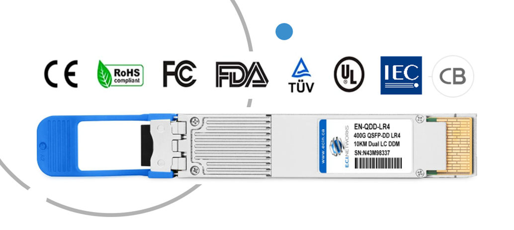
At E.C.I. NETWORKS, all our optical transceivers are CE, FCC, RoHS, and FDA laser compliant, meeting global standards for safety, environmental responsibility, and electromagnetic performance.
Key Certifications
Emissions and immunity compliance for IT and multimedia equipment.
Verified as unintentional radiators with SDoC available.
Safety-certified and laser-classified (Class 1).
U.S. laser safety regulations.
Free from hazardous substances and environmentally responsible.
Available on selected models per regional or customer needs.
Compliance Standards
These certifications ensure our transceivers are safe, interoperable, and built to meet the highest global compliance standards across data center, telecom, and enterprise environments.
Conflict-Free Sourcing
We comply with the SEC Conflict Minerals Rule, supporting ethical sourcing practices for minerals like tantalum, tin, tungsten, and gold.
Quality Certification
At E.C.I. NETWORKS, all our optical transceivers are CE, FCC, RoHS, and FDA laser compliant, meeting global standards for safety, environmental responsibility, and electromagnetic performance.
Key Certifications
Emissions and immunity compliance for IT and multimedia equipment.
Verified as unintentional radiators with SDoC available.
Safety-certified and laser-classified (Class 1).
U.S. laser safety regulations.
Free from hazardous substances and environmentally responsible.
Available on selected models per regional or customer needs.
Compliance Standards
These certifications ensure our transceivers are safe, interoperable, and built to meet the highest global compliance standards across data center, telecom, and enterprise environments.
Conflict-Free Sourcing
We comply with the SEC Conflict Minerals Rule, supporting ethical sourcing practices for minerals like tantalum, tin, tungsten, and gold.
Performance & Reliability
We ensure our optical transceivers deliver exceptional performance and long-term reliability through rigorous testing on industry-leading equipment.
Power & Wavelength Testing
We verify signal strength and wavelength stability to ensure seamless decoding and consistent transmission across the optical path.
Traffic Testing
All transceivers undergo bit error rate (BER) and packet loss testing to guarantee zero data loss and full compliance with Ethernet and Fiber Channel standards.
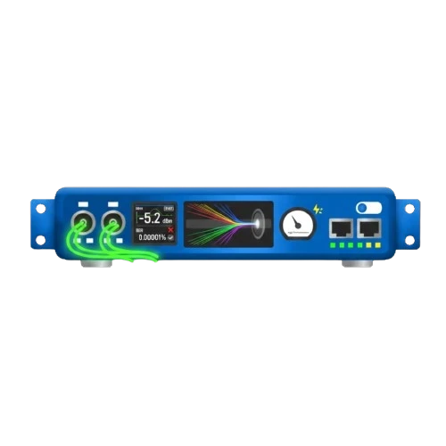
Optical Performance Validation
Our modules are evaluated for signal integrity, eye diagram clarity, and BER, ensuring stable, high-quality optical transmission in all operating conditions.

End Face Inspection
Each module's fiber interface is inspected and cleaned to eliminate contamination and physical defects - a critical step for optimal signal performance and long service life.
Warranty & Compatibility
Optical Transceivers (1G–400G): Lifetime (5 Years)

Zero Risk
Using our transceivers does not void the warranty of your network equipment. Global OEM policies and consumer protection laws (Magnuson-Moss Warranty Act) prevent manufacturers from denying support based solely on the use of third-party components.
Guaranteed Compatibility
Our modules are coded and tested for seamless operation across major platforms including Cisco, Arista, Juniper, HPE, Nvidia, Huawei, and more. This rigorous validation ensures plug-and-play reliability and full compliance with OEM specifications.

Technical Support & RMA
Have an issue? We provide full technical support and hassle-free RMA on all eligible transceivers. Our team is ready to help with any technical questions about compatibility or deployment. contact our technical support: support@ecin.ca
Q&A
Commonly asked questions
No. Under the Magnuson-Moss Warranty Act and similar global consumer protection laws, OEMs cannot void your equipment warranty simply because you use a third-party transceiver. Your equipment warranty remains intact.
Yes. Our modules can be coded for major OEM platforms (Cisco, Juniper, Arista, Nvidia, etc.) and support open networking environments including SONiC.
A compatible generic version can be provided and coded before delivery.
Common 400G QSFP-DD optic types include DR4 for parallel single-mode fiber up to 500m, FR4 for duplex single-mode fiber up to ~2km, LR4 for duplex single-mode fiber up to ~10km, short-reach multimode options such as SR8 / SR4.2, and extended/coherent options such as ZR / ZR+ for longer DCI and metro applications. The attached datasheet specifically covers the EN-QDD-DR4, a 400GBASE-DR4 QSFP-DD module using 4 parallel optical lanes, 1310nm wavelength, MTP/MPO-12 APC connector, and up to 500m transmission over single-mode fiber with FEC.
Choose the 800G QSFP-DD transceiver according to the required distance and installed fiber infrastructure. DR8 is best for data-center links up to 500 m and uses parallel single-mode fiber with an MPO-16/APC connector. 2×400G FR4 supports distances up to 2 km over two duplex single-mode fiber pairs, making it suitable for aggregation and short data-center interconnects. 2×400G LR4 extends the reach to 10 km over duplex single-mode fiber for campus, inter-building, and metro-access applications. FR4 and LR4 connector configurations may use dual LC or dual CS interfaces, depending on the module. Always verify the host platform’s breakout modes, connector type, FEC configuration, power budget, and QSFP-DD800 compatibility before deployment.
Yes. Our modules are coded for the specific platform you select at purchase. They are recognized natively by the switch OS without any additional configuration or commands.
No, E.C.I. NETWORKS 400G transceivers are designed to meet applicable IEEE and MSA specifications, deliver the required 400G data rate and optical reach for their optic class, and support standards-based monitoring such as DDM/DOM. Actual link performance depends on choosing the right 400G type, such as DR4, FR4, LR4, SR8, or ZR/ZR+, and matching it to the correct cabling, optical budget, switch compatibility, and thermal environment.
Yes. We offer full support, RMA service, and warranty coverage on all modules.
Resources
Downloads and documentation